All Cassegrain spectrographs suffer from gravitationally induced flexure to some degree. Thus, designers of these spectrographs must consider this effect and make efforts to see that this flexure does not seriously compromise the performance of the spectrograph. Such concerns are particularly important for large telescope spectrographs for several reasons. First consider simple scaling laws of structures. If one considers a given spectrograph design, and increases all linear dimensions by a factor s, then the gravitational deflections will increase by s2, independent of the details of the structure. All angular deflections will increase by a factor s. The changes in angles of the spectrograph components will cause the spectrum to move, either along the slit or perpendicular to the slit. Either will degrade the performance of a spectrograph. Therefore larger spectrographs are more difficult to design, simply because their angular deformations are larger than smaller ones. In addition, today's largest telescopes are placed at superlative sites. These give images significantly smaller than typical of smaller telescopes. The spectrum stability requirements are therefore tighter because of the better image quality. Finally, on the largest telescopes observing time is at a premium and the utmost efficiency is desired for spectrographs. Thus stability requirements for spectrographs are even tighter, in order to reduce the time spent on calibration of the spectrograph.
In an attempt to satisfy the extremely demanding stability requirements for ESI, we have developed a spectrograph design using the most efficient structures, space-frames. These structures are ideal for supporting localized loads (mirrors, gratings, and cameras) with the maximum stiffness per unit mass of support material. They are also relatively simple to design and build and their performance can be accurately modeled with finite element methods. Thus the structures often can be optimized in the design process to achieve specific performance goals.
Further improvements in performance can be achieved if the spectrograph has active compensation for any residual flexure. D’Arrigo, et al (1997), has described the value of such designs for a spectrograph for the Gemini Telescope. ESI will have an active optical system to achieve the best possible performance.
Miller and Epps (1998) give a description of ESI and its scientific capabilities. ESI will be an off-axis (5-arc minute) three-mode instrument with high resolution, low resolution and direct imaging capabilities. The collimator mirror is 0.58 m in diameter to accommodate the 2 x 8 arc minute field. The collimator and camera have focal lengths of 2.286 m and 0.308 m respectively. A sensitivity analysis of various components by Sutin (1997) led to the selection of the collimator mirror as the most effective active optic component. The aim was to find a component that, when moved, would compensate, with the smallest higher order residuals, for the motion of any of the other optical components.
The intention is to calibrate the active correction for gravity flexure and then apply these corrections in an open loop fashion. In order for this to be practical, the instrument must be built with very low hysteresis in to maximize the repeatability of the flexure. Again, space-frames are an ideal way to build hysteresis free structures, so long as care is used in the joints. For the gravity loads expected, the structure’s response should be essentially perfectly linear with load.
The final scale at the camera CCD is given by
![]()
where
d is the displacement on the CCD, q is the angle on the sky, and ftel, fcam, and fcol are the focal lengths of the telescope, camera and collimator. This neglects the anamorphic effects of the dispersing elements. The telescope focal length is 149.6 m. The CCD will have 15 µm pixels (0.154 arc seconds/pixel). The goal for any 2 hr observation is that the spectra will be stable on the detector to within ±0.08 arc seconds (peak to valley) without flexure compensation and within ±0.04 arc seconds with (open loop) flexure compensation.
In an effort to minimize the effects of flexure in the instrument a "space-frame" structure was adopted as the backbone of ESI. The virtue of the space-frame approach is that all elements carry only tensile and compressive loads. Structures without any bending moments do not have higher order deflection sensitivities to the lengths of its members. In fact, the deflection is linear with the length and cross-sectional area of the strut. More exactly, the deflection (
d) of a member under pure tension or compression is:![]()
Where P is the applied load, L is the element length, A is the cross sectional area and E is the elastic modulus of the element. Pure tension and compression members are not the only requirements for a structure to be considered a space-frame. By using slender elements the bending stiffness of the members becomes negligible, and thus the space-frame acts like a truss with pin joint connections. In these structures it is critical that the centerlines of struts intersect each other accurately, at the nodes of the structure. The design of the joint that connects multiple struts at a node is often the most difficult part of the design process. When a space frame is used to attach an optical element to the rest of the structure it is essential that the connection be made in a determinate fashion. The number of struts should equal the number of constraints that will just define the location of the optical element. If the connection is made in an indeterminate way, the extra constraints can act to apply deforming forces to the optical element. With a determinate structure, any changes in the lengths of the connecting members will only cause motion of the optical element, but no distorting forces.
To attain the flexure and no-flexure-control specification, all possible optic mounts are being designed using space-frame structures to attach them to the mainframe. The mainframe represents the largest determinate structure in the instrument and is described by Bigelow and Nelson (1998) in a separate paper given at this conference. A similar challenge existed for the mounting of the two large cross dispersing prisms used for the low-resolution mode of ESI. Sheinis, Nelson and Radovan (1998) present a detailed description of the prism mounts at this conference.
When the optical design for ESI was developed, the collimator was placed close to the end of the allowed instrument space envelope as defined by Keck Observatory. This gave the largest beam size on the grating. Unfortunately, part way though the project, it was found that the stated space envelope was incorrect. Originally there was to be a mirror cell supporting the collimator mirror. With the reduction in available space, space for a mirror cell was extremely small, and space for three actuators behind the mirror to control tip-tilt and focus was unavailable. As a result, the actuator locations were moved to the nodes of the mainframe structure and the mirror cell was simplified to three support points at the edge of the mirror.
The range of focus was set at ±25 mm which gives out of focus images of ±2.30 arc seconds. This range easily accommodates any tolerance buildup and flexure compensation needed and also provides out of focus images for diagnostic purposes. A tilt of the collimator by
f is equivalent to motion on the sky (q) of
![]()
To achieve the flexure compensation precision, we want to tilt the collimator in sky moves of roughly 0.01 arc seconds, or collimator tilts of 0.327 arc seconds. With actuator separation of 1200 mm this corresponds to actuator steps of 3.3 µm.
In order to achieve the desired accuracy of correction, we must keep hysteresis and slip to levels below this value.
 ESI plans to take full advantage of the virtues of space frames by supporting the collimator without a cell. By gluing 3 Invar pucks at the correct locations to the Zerodur collimator, support can be provided by six struts that attach to these pucks. Each strut acts as a single degree of freedom constraint. To assist in the alignment and fabrication of the off axis parabolic collimator, the collimator mirror includes a precision hole along its optical axis. The as-built collimator is a section of a 0.58-m diameter disk that includes the active area and the alignment hole. The mirror is shown in Figure 1.
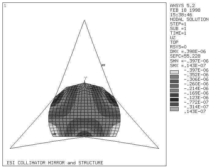 The puck locations were adjusted to give the minimum surface deflection under gravity. This was done with a finite element model of the collimator. For the collimator shown in Figure 1, the optimized support solution will have a maximum peak-to-valley deformation of 250 nm over the active area. This occurs when the telescope is at the zenith. In Figure 1, zenith pointing corresponds to gravity in the Z direction. Contours of the deformed shape (Figure 2) show that the primary effect of the deflection will be low order deformations such as focus and astigmatism. A single star has a footprint on the collimator about 0.15 m in diameter. Since this is significantly smaller than the active area, the deformations have two different aspects. First, they can degrade the image quality of single stars. The maximum slope variation over any single footprint is 0.43 arc seconds, which degrades the images by 0.012 arc seconds. Second, the different mean slopes can move star images with respect to each other (field distortion). The maximum effect is about 0.01 arc seconds.
Each of the three pucks acts as a node on the collimator. The use of Invar with a carefully controlled bond thickness assures a minimal thermal effect at the connecting interface to the collimator. Invar-to-Zerodur epoxy connections have proved to be an extremely reliable and low stress joint in use at the Keck Observatory. Iraninejad et al, (1987) discusses optimization of the bond thickness to minimize stress.
The ESI collimator design includes a safety system composed of two thin plates attached to each puck with a slip connection that does not add any constraints (Figures 3 and 4) but supports the mirror in case an epoxy joint should fail.
The collimator is supported by 6 struts that just constrain it. Only tension and compression forces along each strut are experienced by the collimator. Because the system is determinate, the collimator experiences no additional forces if the struts change length or move. Thus no uncontrolled deforming forces can be experienced by the collimator. These struts attach to the main frame at its 3 lower nodes. By moving these nodes individually the collimator motion in tip, tilt and piston can be controlled. Because the actuators are close to the plane of the collimator, tip and tilt introduce negligible translation of the collimator.
To minimize unwanted thermal effects the entire instrument will be insulated and no significant heat sources will be within the insulated volume.
The decision to place the three actuators at the nodes on the mainframe placed significant mechanical and spatial requirements on the struts used to support the collimator. With careful 3-D modeling in AutoCAD possible configurations for the mainframe and collimator support were checked to insure the light beam was not vignetted. The stability of each possible solution was checked quickly by building ½ scale models of the space frames using welding rod and a hot glue gun. This was very valuable in determining if the structure had a redundant support. Once the design passed this test a FEA model of the collimator and supporting struts was used to predict the image motion in the slit direction and dispersion direction for three orthogonal gravity vectors. The summarized results in table 1 are for all six struts with a diameter of 9.5 mm. Optimization of the collimator support assumed the mainframe was infinitely stiff.
The FEA contour in Figure 5 is for zenith pointing shows that flat edge of the collimator drops by 14.7 microns more than the opposite edge which rotates the collimator 6.9 arc seconds about the x-axis. This motion will be one of the largest contributors towards the image motion without flexure control. One advantage of a space frame is that the strut cross sectional area can be tuned to minimize the rotation. In our situation where rotations matter for 3 load cases, we have 6 tilts we would like to eliminate. It is not possible in general to eliminate all tilts by adjusting the 6 strut cross sectional areas. However, even with imposed bilateral symmetry we can adjust two cross sections to eliminate any two tilts, or minimize any desired function of the tilts. For example, changing the two struts attached to the flat edge to 12.7 mm diameter (figure 6) reduced the rotation to 0.7 arc second. Table 2 summarizes the collimator rotation and the resultant image motion on the CCD.
Since each strut supporting the collimator constrains only one degree of freedom the strut must be flexible in all other directions. For the ESI collimator this is complicated by the fact that each actuator at the mainframe node can move 50 mm. Flexure corrections during observation will require only micron sized motions of the actuators, but if something goes wrong in the servo system one actuator could travel 50 mm beyond the other two, tilting the collimator by approximately 3 degrees. Although the strut support protects the collimator from any bending moments, each strut will see large stress that could result in yielding of the flexures or failure. To design a strut that can survive this motion without yielding, pairs of orthogonal cross flexures are added to each end of the strut. Figure 7 shows the details of one end of each strut. Each pair can bend to remove one rotational and one translational constraint. The fifth constraint is removed by the low twisting stiffness of the flexures in each strut. The design was optimized in a spreadsheet to check the bending stress, torsion, compressive stress and buckling of the flexure. Each flexure was modeled based on formulas from Vukobratovich (1993). Material was evaluated based on the ratio of the yield strength to elastic modulus otherwise known as the reduced tensile modulus. This figure of merit is 7.27x10⁻³ and 4.39x10⁻³ respectively for Titanium 6Al 4V and 17-4 PH stainless steel. At first Titanium appeared to be the better choice because it had a greater safety factor in yielding and did not need to be heat-treated to attain its high yield strength. Even though the reduced tensile modulus is lower for stainless steel it was used because it will carry twice the load before buckling. The longest struts for the collimator support have a slenderness ratio of 307. Euler column bucking predicts a critical load of 390 newtons for stainless steel and half of that for titanium
To facilitate initial collimator alignment, each strut is connected to the nodes on the collimator and mainframe with a fine pitch left and right hand threaded end. Turning a strut will change its length and move the collimator. Locking nuts are used at both ends. To make this a one time only process a removable puck was added to the design to interface with the invar puck. The struts connect to this puck which is attached to the invar puck by a pinned and bolted connection. Prior to removing the collimator for coating a set of fixed points on the slit can be illuminated and their position on the CCD recorded. The pinned joint can be disassembled to remove the collimator for coating and reassembled without realigning the spectrograph. All that is necessary is to adjust the collimator so that the calibration points on the slit are in the same place on the CCD. The new settings for the three actuators are then entered into the lookup table as an offset.
The actuators are designed as three independent cartridge assemblies that mount in the lower tubes of the main frame.
The line of force of each pair of collimator support struts passes through the node in the main frame when focus is at the nominal setting. When the actuators move from nominal focus the small moments transferred to the main frame have no noticeable effect. Each assembly is mounted to the inside of the tube with six push-pull screws to allow alignment of the actuators to the optical axis of the instrument. A complete cartridge assembly is composed of a THK High Precision ball screw (6-mm lead) slide driven by a Galil servomotor (4000 count/ revolution encoder) through a 100:1 gearbox (figure 8 and 9). Included in the assembly is a 1/10-micron Renishaw linear encoder that forms the second branch of the dual servo  loop. The assembly also includes primary as well as secondary limit switches and mechanical hard stops. Due to the large reduction through the gearbox and lead screw, six motor encoder counts equals one reinishaw count. This servo system is capable of repeatable positioning to 0.04 of an arc second of collimator tilt over the entire 50-mm range of focus.
Prior to assembling the collimator support each of the cartridge assemblies were bench tested to insure that the 3 actuators could be moved to provide focus without tilting the collimator. Testing showed that each actuator could be driven to any desired position within 2 Renishaw counts which corresponds to a tilt error of 0.04 arc seconds. When two of the actuators where slaved to a third for focus motion the total error increased to 3 encoder counts (0.06 arc sec tilt)
Testing of the entire system was conducted with an aluminum dummy in place of the real collimator. Each actuator was run to its limits to check the stability of the structure in the most extreme positions. The first natural frequency of the collimator support has been measured at 75 Hz. This was measured by capturing the output of a Mahr gauge, mounted between the collimator and the main frame, with a digital storage scope. Mahr gauges, which are Linear-Variable Differential Transformers (LVDT), were also used to measure actuator hysteresis. Tests of the THK actuators measured 1 micron of hysteresis, which is 3 times better than the actuator specification.
We attempted to measure the hysteresis of the assembly using a Davidson auto collimator fitted with a CCTV camera. The Davidson was placed on top of the main frame and directed at a return flat on the collimator. Using spring scale a 300 newton load was applied to the collimator in orthogonal directions. Each time the reticle returned to the starting mark on the monitor. We concluded that the hysteresis was below the 1 arc second limit of this measuring technique. The final test planned for measuring the hysteresis will replace the auto collimator with an interferometer to give us resolution below an arc second.
Additional testing confirmed the predictions of the FEA model for the rigid body motion due to strut stretch for the three orthogonal gravity vectors. At the time of writing the larger diameter struts that reduce the collimator rotation to 0.7 arc seconds for zenith pointing have not been built. The final dimensions of the struts are being used as one tuning parameter in a complete FEA model used to predict the total image motion due to all flexure in the spectrograph.
The use of space frames to support ESI’s collimator has produced a very stiff structure that can be moved without introducing bending moments and causing image degradation in the collimator. The geometry of the support has been designed to allow control of three degrees of freedom providing tip and tilt for flexure compensation and piston for focus. The system has proven to have hysteresis below 1 arc second and a measured first natural frequency of 75 Hz. This type of determinate structure eliminated the need for a collimator cell and reduced the total supported mass by at least a factor of two. Space-frames provide engineers with a powerful tool to build larger structures with deflection responses that scale linearly with the length of the members.
Thanks to Carol Osborne and Mary Poteete for their contributions towards the detailed drafting of parts drawings and preparation of illustrations for this paper. Thank you Jack Osborne for your technical input and editing of this work.