5.1 Entrance Hatch
The entrance hatch is shown in Figure 1.3. The hatch will be air-operated with an opening time of approximately 10 seconds. The entrance opening is 31" by 31" and there will be two interlocking doors which will not obscure the primary mirror when open. There will also be light and dust seals when closed. There will be latches to hold the doors open and latches to hold the doors closed. These will prevent the doors from moving if the air supply system fails.
Calibration lamps will illuminate the inside of the hatch doors. The inner surface will
be reflective white paint. The hatch should be sufficiently light-tight to allow calibration
observations in the daytime.
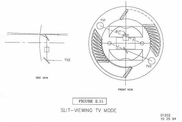
5.2 TV Guide and Acquire
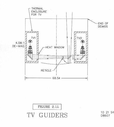
The TV system is shown in Figures 2.21 and 2.22 and described in Section 2.10. We will
purchase two complete systems consisting of a Photometrics CCD camera, electronics
control and cooling system.
The current baseline TV system is this:
We will interface the Photometrics TV cooling to the DEIMOS cooling system. There
will be an insulated box with three radiators and a mixing fan to circulate air between
them. One radiator will have Observatory coolant flowing in it, and each of the TV cameras will have a radiator for its closed cycle cooling system.
Each camera will have one 8-position filter wheel. The filters will be either 2" diameter or 2" square. The individual filter holders can handle up to 0.4" thick filters.
Focus will be by rotating the Canon (or equivalent) lens focus ring. There will be one
motor, limit switches and a center-finding fiducial switch (optical interrupter).
There will be an aperture control motor (has no limit switches). This is also built into
the lens. The aperture control is needed since there are no neutral density filters, only
color filters. Total exposure control is a factor of 26.
The 2 TVs will be near the opposite edges of the 20' Keck field for better rotational
control.
There will be two folding flat mirrors for each TV (4" x 6" each).
Each TV light path enters a sealed, insulated enclosure at the edge of the focal plane
area. Quartz windows seal the TV enclosures from the slit-mask focal plane area. This
will reduce heat transfer to or from the focal plane.
Problems caused by TV stage flexure will be eliminated by using a rigid reticle frame
at the location of the telescope focus, which does not move. Each TV will look through an
illuminated grid mounted to each reticle frame. The reticle can be flat. The grid illumina-
tion will be adjustable and controlled remotely.
A movable pair of mirrors will convert one TV into a slit-viewing TV. The scale and
FOV are TBD. The slit-viewing field and offset field will be parfocal (refer to Figure 2.21.).
The front window of the camera head will have a wedge to allow use with narrowband filters.
5.3 Internal Calibration Lamps
Calibration lamps will illuminate the inside of the hatch doors. Lamp brackets will be
located in the pre-slit area. Lamps provided will be neon, helium-argon, mercury-cadmium and quartz-iodide. They can be turned on in any combination. Exposure times for
adequate S/N should not be longer than 60 seconds and preferably 10 seconds. There may
also be a lamp illuminated through a Fabry-Perot etalon.
The quartz-iodide should be color balanced for the region 4000� to 1 µ. Lamps will
be easy to change and inexpensive.
5.4 External Calibration Lamps (Dome)
In addition to the internal calibration lamps, there will be an illuminated circular spot
on the dome.
The light sources will be projector lamps, probably mounted to the telescope. There
are two types of light source: a continuum lamp (quartz iodide) and an etalon. The projectors will be attached to the center section of the telescope tube assembly. This is like the
application in LRIS.
Each light source type will be provided via two projectors, one for each half circle, or
4 projectors in all. Use of the two lamps separately provides a Newell-type focussing test.
Each projector can be turned on and off independently.
The quartz-iodide lamp should be color balanced for the region 4000� to 1 µ. Exposure times should be no longer than 60 seconds, and preferably 10 seconds. Lamps will be
easy to change and inexpensive.
5.5 Slitmask Handling
Two mask storage cabinets will be integrated into the pre-slit area of the rotating structure. They are shown schematically in Figure 1.3. We will use the full-size DEIMOS
model to develop the handling details. Each cabinet will hold 10 slitmasks. Three will be
permanent, and up to 7 or 8 will be changed each evening.
Six functions are required to get a slitmask into place:
Time for full mask insertion/removal will be 73 seconds to remove one mask and
install another. See the end of this chapter for a timing budget.
It will be possible to insert or remove masks at any instrument rotation.
There will be counterweights so that storage cabinet rotation does not change the
instrument balance. There will also be dummy slitmask frames when a full complement is
not used. This will keep each cabinet balanced.
Slitmasks will be manually loaded and unloaded from the outside of DEIMOS through
two doors. First, the instrument rotation will be halted at one of the load positions. Next,
the drive will be locked out and a positive locking pin engaged. To get at the inner slitmask cabinets there will be one access door for each side. The storage cabinets can be
manually rotated once the drives are switched to local control. Old masks will be
removed and new masks will be installed. Each mask will be designed so that it cannot be
loaded upside down or backwards. After loading the new masks, locking the doors, the
parking pin will be removed, and all of the drive motors will be returned to computer control (a buzzer will remind the user to do this). It will take approximately 25 minutes to
load one set of 14 new masks. Further discussion of the error budget for slitlet location is
given in Section 5.25. (See also Appendix E, Section 1.2: 0.0005" in the x direction
(10" direction) and 0.005" in the y direction (30" direction).)
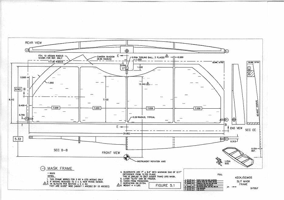
5.6 Slitmask Blanks
The focal plane has an 83.6" radius of curvature. We will refer to it as a plane even
though it is spherical. The sagitta across the full 20' field is 1.77". The sagitta for a single
slitmask is 1.60".
The slitmask frame is about 30" by 9.6" and about 1.9" thick. There will be four
roughly rectangular apertures in the frame. The mask material will be 0.003"-thick 304
annealed stainless steel. It will be cut into approximately 7.25" by 9" sheets. These will
be flat. (We will investigate the idea of bumping them into a spherical shape before applying them to the frame, although storing will be easier if they are flat.) They will be
clamped over 4 rectangular holes and held with appropriate hardware. A recent test has
showed this to be feasible. The webs in the frame will be about 0.20" wide and will cast
shadows onto the CCD mosaic exactly within the 0.040" wide gaps.
We will need hundreds of these masks since they will probably not be reusable. There
will be many fewer frames, however. The first mask frame will be made from a solid aluminum plate. Each mask will have three tooling balls. The balls will locate the plate in
the computer-controlled milling machine (NC mill). The mask frame will be machined
from the solid piece in 6 to 8 hours (unattended). The tooling balls will next locate the
frame in the laser slit cutter and finally, the balls will provide location in the focal plane of
the telescope. We will investigate cheaper ways to make these frames, like casting or
injection-molding. The initial complement of mask frames will be 40 for the dual spectrograph, 4 permanent and two sets of 8 changeable per beam
The three permanent masks on each side will be chosen from a complement of four
choices:
The long-slit masks on one side will have reflective areas near the center of the slits for
the slit-viewing TV.
The locational tolerance of the mask surface in the focus (z-axis) direction is 0.030" (
0.015"). This corresponds to a defocus blur of 25 m, or an increase of 0".035 in image
diameter. The entire mask must conform to the focal surface to this tolerance. The accuracy of the manufacturing process can be checked by running slitmasks through our profilometer.
The masks will probably not be reusable after being removed from the frame, as the
material is too fragile. However, we will try to develop an inexpensive storage medium.
We are also considering plastic for the mask material, which would be more durable. The
permanent masks will be manufactured from stronger material.
Bar codes or their equivalent will be impressed on the slitmasks. Readers will be used
in both focal plane locations as a final check to see that the proper masks have been
installed.
5.7 Slitmask "Cutter"
Slitmask "cutter" is a generic term for this machine. Our current plan is to use a laser
cutting machine. The laser-cutter device is described in more detail in Chapter 8.
We will work with a vendor to specify, test, approve and calibrate this machine. The
range of travel needed is 29" by 10" with 2" of z-axis motion. We plan to purchase and
receive the Cutter by mid-1995 so that we will have 3 years' experience using it.
Algorithms will be needed for converting Right Ascension and Declination coordinates to slitlets. The Canada-France-Hawaiian Telescope has something like this and we
will investigate their system. We will also investigate similar code in use for LRIS.
A typical slitlet will be rectangular of size 0.029" x 0.43" (1" x 15"). With 15" long
slitlets, there would be 64 slitlets per mask. A typical slit (1" wide) should be uniform in
width to 1%. Sides should therefore be smooth to +/- 7 µ. Slitlets should be located
within each mask to an accuracy of 0.0001" (0".035) in x and y. The cutter should also be
able to cut slits of arbitrary shape if possible, e.g. tilted slits, curved slits, and other shapes.
The Cutter should also be able to make a bar code at the same time the slitlets are created
(see Chapter 8).
Since there will be up to 16 masks made for one night (8 each side), speed of manufacture is an issue. We have received a proposal and quotation from A.R.T. (Advanced
Recording Technologies in San Diego, CA). The machine they have proposed building
for us is a laser engraving machine. The material used in their study was 0.003" 304 stainless steel. They claim to be able to produce 10 masks in 8 hours. This is barely workable.
More details are given in Chapter 8.
We will provide water cooling for the Cutter.
The machine may be installed at the Mauna Kea summit or in Waimea. The project
needs to be consulted as to its final location and the nature and training of the personnel
who will operate it.
5.8 Window
A window will be located behind the slit (see Figure 1.3). This serves to keep the interior of DEIMOS clean. The material will be BK-7 or similar.
The window will be roughly circular: the diameter will be about 35" with 2 cutout
notches to clear the light beams at the gratings. The window will also have an 8" diameter
central hole for mounting. We will also use this central hole for collimation. A dust cap
will seal this hole. The thickness of the window is 0.5". It will weigh approximately 40
pounds.
The window will be Sol-Gel coated (for anti-reflection). This means that slings and
fixtures for handling at Lawrence Livermore National Lab (LLNL) will be required. A
special clean container will also be needed.
5.9 Collimator Mirror
The collimator mirror is shown in Figure 1.3. The baseline design uses a 4" thick
blank. It is 46.3" in diameter and weighs about 500 lbs. A 4" diameter central hole will
be drilled out for instrument collimation.
We are investigating the use of a Zerodur blank. Zerodur is the preferred material
because of its very low coefficient of expansion. It makes fabrication and testing cheaper
(and quicker). The blank will be generated by an outside vendor.
Mirror support:
The mirror surface shape is elliptical. We have tentatively set the focal length to be
86.5". Sagittal depth will be 1.49", and all corners will have 0.5" bevels.
The coating will be silver (with no overcoat).
Lick Optical Shop support:
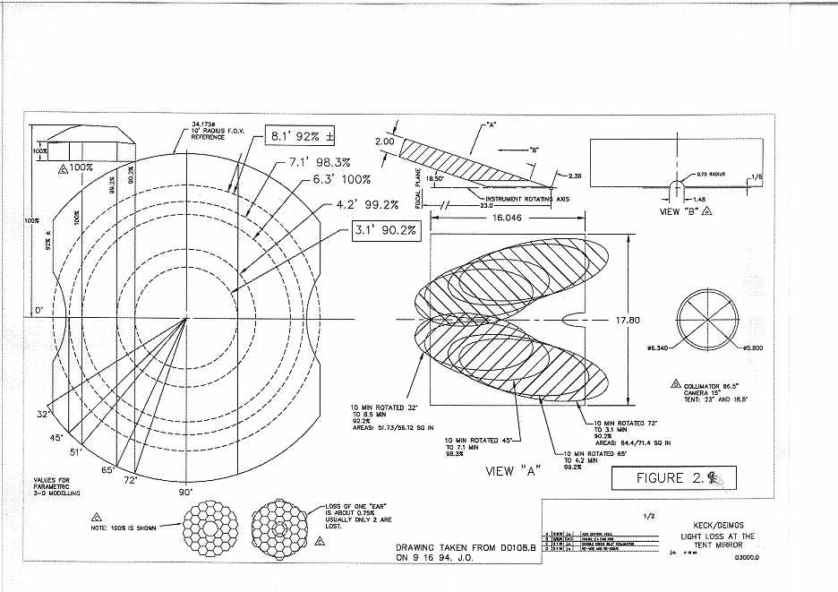
5.10 Tent Mirrors
The tent mirrors are shown in Figures 1.3 and 2.9. They may be the active optic for
the FC system to correct for flexure within the spectrograph.
These mirrors will be Zerodur. There will be a large back bevel on the "sharp" edge:
18.5 degrees included angle. The other three edges will be 90 degrees included angles. Mirror size will
be 16" long by 18" wide by 2" thick. Approximate weight will be 50 pounds per blank.
Back supports will see positive and negative forces. We will use glued-on invar pads (like
the HIRES gratings, which are about this same size). There will be a 1/4" gap at the joining plane (1/8" each mirror).
There will be a clear hole of about 1.5" diameter on the instrument centerline for
checking telescope alignment. Thus, each mirror will have a semi-circular cutout on the
"sharp" edge. A removable light baffle will be located close to this sharp edge and extend
down to the collimator mirror. It will keep light from one side from entering the other side
of the dual spectrograph.
Both mirrors will have a silver coating (no overcoat).
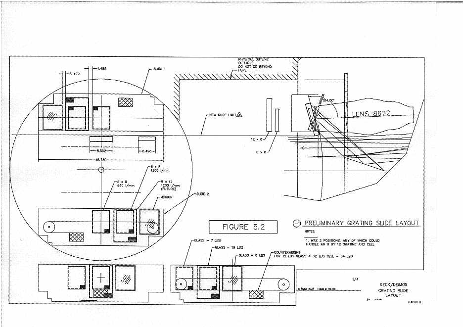
5.11 Gratings, Flat Mirrors, Mounts, and Grating Slides
The gratings and grating slides are shown in Figure 5.2. Each slide is motorized with
three positions:
There will be limit switches for position readout and end-of-travel stops.
The rulings will be standard replications by Milton-Roy (MR) in Rochester, New
York. One or more new masters may be required in the 6x8 size.
The gratings will install into sub-cells that insert into the grating slide mechanism.
The alignment into the sub-cells will be performed by Lick Observatory technicians at
UCSC. The installation tolerance is 1' (?). We plan to use the Zygo Interferometer and
special tooling to do this.
The exchanging of gratings into the instrument will be done by users or technicians.
This will be a simple procedure:
Each grating position in the slide will have a tilting function: one of three or four fixed
angles can be selected for each grating. The time it takes to rotate between angles will be
on the order of 10 seconds. The 1200-line grating will have a different set of angles from
the 830-line grating. Each sub-cell will have locating buttons built into the rear for angular position stops. Each set of buttons will be unique to the grating ruling and establish the
possible rotation angles. The widest range of angles is 15 for the 1200-line. The 830-line
is 7, and the 600-line grating may not move at all.
The flat mirror will be 7" (?) by 9" (?) by 1" thick. This mirror is located at the exit
pupil formed by the collimator mirror. There should be no light loss at this element.
The linear grating slide will have a positive clamp. The allowable flexure spec for
each grating and for the flat mirror is TBD. The grating stage will be counter-weighted to
prevent an out-of-balance condition in the instrument. The grating drives and slide will
operate concurrently with other motions.
The areas around the gratings and the cells and sub-cells will be painted black with
low reflectance paint. For possible future narrow-band imaging, efficient light traps will
be built into the grating slide in the area behind the cells.
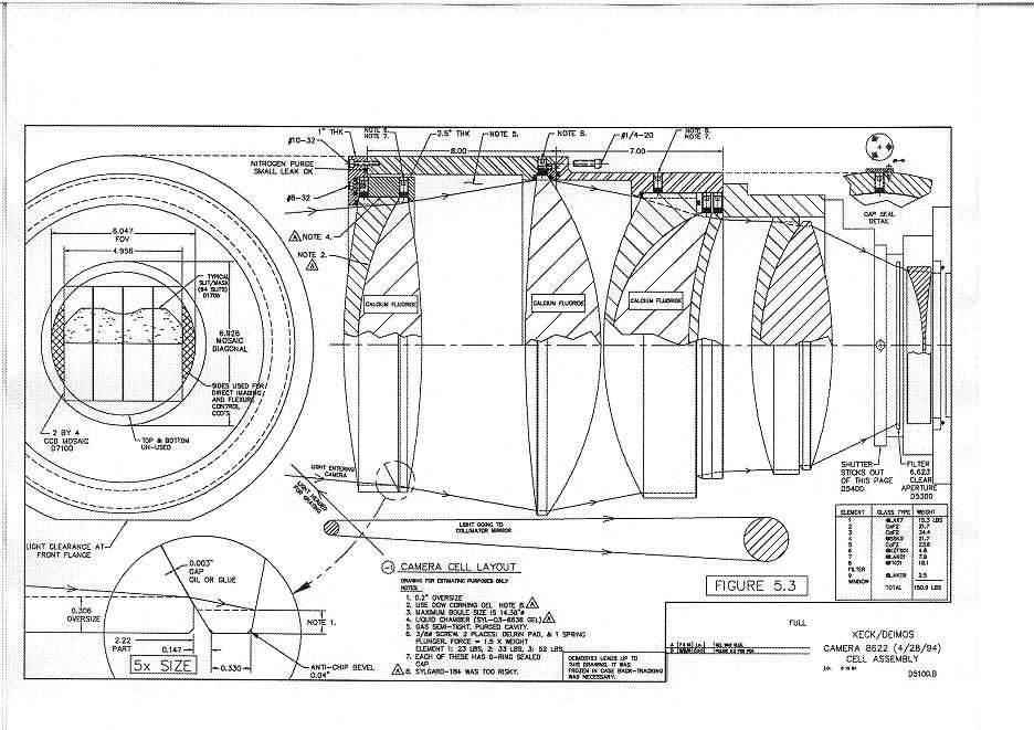
5.12 Camera Lens Cell
The camera lens consists of 8 lens elements, a filter, and a plane-parallel dewar vacuum window. There are 2 doublets, a triplet, and a singlet. The contacting surfaces will
be coupled. Preliminary tests have ruled out several bonding agents. A likely candidate is
Sylgard-527 Gel. This provides optical coupling but no mechanical strength.
The camera lens cell is shown in Figure 5.3. It will be aluminum. The axial spacings
of the individual lens elements (there are 8 of them) will be adjusted by cutting spacers to
the exact length.
The lens cell will not include a heater.
The three calcium fluoride lens elements must be sealed and kept purged with inert
gas. There will be O-ring seals within the lens cell. The individual lens elements will be
anti-reflection (AR) coated, some with Sol-Gel and others possibly with multi-layer coatings.
The camera lens will be tested at 20 C at UCSC. A testing plan will be devised so
that performance at 3 C is predictable from these tests.
The final element or "field flattener" will not be located inside the vacuum housing.
This is to enable direct inspection of the mosaic alignment and also to allow a UV flood
through the dewar window if necessary.
We will need lens assembly fixtures, lens testing hardware, lens coating slings and
special lens element shipping boxes.
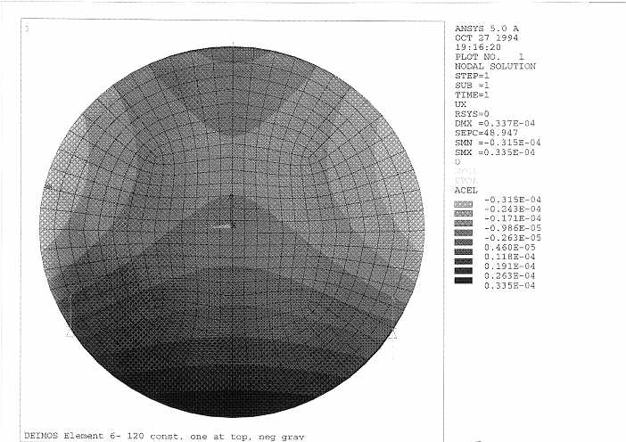
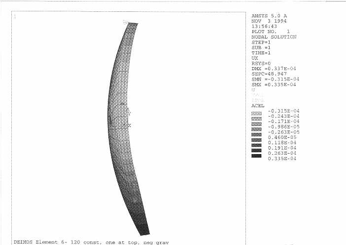
5.13 Camera Lens Analysis by Finite Element Analysis
Two lenses in the camera may be difficult to support. Since the optical coupling material offers no strength, each element must be self-supporting. To check this, a finite element analysis has been carried out.
The analysis was done by Bruce Bigelow at University College London and was
checked by David Cowley here at UCSC, both using ANSYS Version 5. Some differences
exist in the detected shape of the deflection diagrams, which are likely caused by differing
boundary constraints.
Typical output is shown in Figures 5.4 and 5.5. Units are inches. The element shown is
the 6th lens in the camera (present design is number 8622 by Harland Epps, dated 4/28/
94). It is the thinnest and one of the most difficult to hold, as it cannot be supported
through its center of gravity with simple two-point support system. The magnitude of the
deflection across the lens is of the order of 2 waves (5000 �). Under the guidance of Harland Epps, Brian Sutin is analyzing the effect on the image quality of such a deflection.
We are striving for deflections less than one-quarter of this value.
Lens element 4 was also analysed using FEA and was shown to have a worst case
deflection of about 0.5 waves.
If these deflections cause serious problems, better support systems will be explored.
Increasing the thickness of the elements will also be explored. An increase in thickness of
1.5 times would be expected to reduce the flexure by about a factor of 4. Early results of
an optical analysis indicate that the magnitude and shape of these deflections cause no
image quality problems.
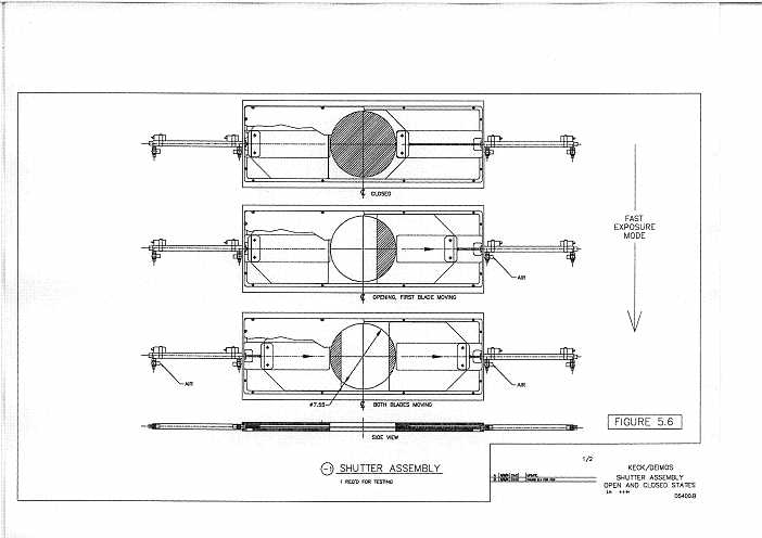
5.14 Shutters
The shortest possible exposure will be 0.10 second (100ms). The maximum absolute
shutter error is +/- 10ms. The shutter will produce 1% exposure uniformity across the CCD
mosaic for a 1 second exposure. The shutter is located ahead of the filter slide. The shutter will have a 7.5" diameter clear aperture and operate in all orientations. There will be
no adverse temperature effects on the shutter mechanism.
As there are no commercially available shutters with this performance, we are designing our own (Figure 5.6). The design is a copy of the new large 2-bladed shutters built for
the 120" Multi Object Spectrograph at Lick Observatory (3" diameter). These shutters
have pneumatic cylinders which drive titanium blades. We have seen no vibration problems.
Figure 5.6 shows the shutter in open and closing positions. We do not expect that the
shutter will cause instrument balance problems, and so there will be no counter-weights.
The shutter timing signal is controlled by the UCSD CCD Controller Board (?).
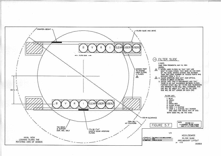
5.15 Filters and Filter Slides
To minimize filter size, the filter slide will be mounted immediately to the rear of the
shutter. The filters will be 7.0" in diameter (or 7.0" by 7.0" square). A 6.62" clear aperture is required for Epps' design 8622.
The filter slide has seven positions (see Figure 5.7): one position of clear material, four
photometric filters (BVRI), and two user locations.
The user will have ready access to a total of 4 locations, two at each end of the slide.
These will contain the two nominal user slots plus two of BVRI. To change filters, the
instrument will be halted at either of two specified positions. Filters are manually
exchanged. After access doors are secured, the instrument rotation will be re-enabled.
This operation should take less than 5 minutes. The central three filter slide positions are
accessible only through a large, removable hatch. This requires more time and small hand
tools.
Filter thickness is approximately 0.5" set by the B filter, which is the thickest. All filters must have the same optical thickness to within 0.005", corresponding to a depth of
camera focus of 25 µ. Changing filters will not change spectrograph focus by more than
this amount.
The filter slides will be counter-weighted to maintain instrument balance. There will
be limit switches at both ends of travel. The time to change between adjacent filters will
be 5 seconds. The time to change from one end filter to the opposite end will be 30 seconds. The filter changing will be concurrent with other instrument stage motions.
5.16 Dewars
The dewar has a big window: 7.1" diameter by 0.35" thick.
The dewar includes two CCD's for flexure correction. These are located next to the
main mosaic.
The present dewar design uses liquid nitrogen (LN2) cooling; hold time will be 24
hours. The volume of LN2 will be approximately 4 liters (per dewar). The LN2 container
will be designed so that no variable torque is exerted on the dewar as the LN2 charge evaporates. This is to avoid rotating the detector as LN2 evaporates.
There will be a Varian 2 liter/sec ion pump for each dewar to maintain a vacuum of
10-8 torr.
Focus motion:
There will be a vacuum pumping station (oil-free and private like HIRES). This will
employ a molecular drag pump with piston and flapper valve fore pump. This pumping
station will be shipped to Hawaii. It will not include a leak detector. The leak detector in
the UCSC shops will be used during fabrication of the dewar.
There will be an aluminum-to-stainless transition tube for the inner LN2 can.
The pre-amp chassis will be attached to the dewar bodies to minimize electrical noise.
The CCD controller chassis will be located near the dewars, in an insulated housing
which will be maintained above 5 degrees C. This minimum temperature requirement is for the
electronics components. An enclosure around this housing will be cooled to control local
seeing inside DEIMOS.
Closed-cycle coolers will be investigated as an alternative to LN2.
5.17 Frame, Skin, and Access Panels
Must be absolutely light-tight and dust-tight when all panels are installed.
The instrument will be purged with N2, so sealing is important to keep gas flow to a
minimum.
Everything inside will be painted deep black. Internal light baffles will be supplied.
Access doors should be situated to allow visual inspection of fiducial laser beams hitting the collimator, tent mirrors, flat mirrors and the center of the camera apertures.
Mechanical discussion of the Frame is given in Section 5.24.
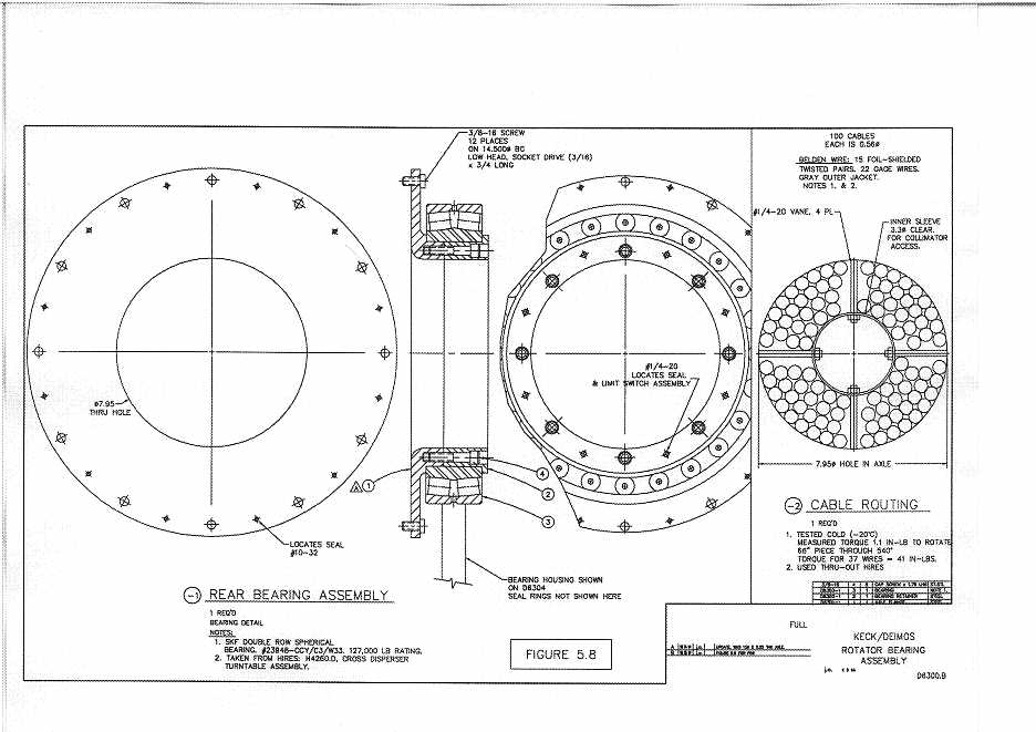
5.18 Drive and Support
The instrument will be supported at the slit end by two rollers separated by 90 degrees rolling
on a 73.8" diameter hardened steel disk.
Support bearing at rear:
Remove and Replace System:
5.19 Cable Access
5.20 Electronics Vault
We have purchased a Bally building exactly like HIRES: 6 feet by 6 feet by 9.5 feet
tall. This is the smallest size modular building available. The Vault has a door for access.
This building is expandable in 23" panels. We plan to use the (HIRES) Electronics Vault
freezer for the extended cold test (down to 5 C at UC Santa Cruz). This freezer will not
go to Hawaii. The Vault will be bolted to the Nasmyth platform and not move. Figures 1.4 and 1.5 show its location relative to the telescope.
The purpose of the Vault is to thermally isolate the Instrument Controller electronics
and associated power supplies and motor drivers from the telescope and dome. It is not
feasible to move these items to the downstairs Control Room. The temperature inside the
Vault will always be between 5 degrees C and 50 degrees C set by the ratings of the electronic components). The UPS, which is always on, generates enough waste heat to keep the contents
above 5 degrees C.
All electronics will be contained inside the Vault except the CCD pre-amps and the
CCD controller chassis, which must be "close to" the CCDs. The CCD Controller VME
Crate will be located in the control room. Fiber optics will connect the VME Crate to the
Vault via the telescope azimuth cable wrap, about 300 feet long.
The Vault room will be cooled by the Observatory ethylene glycol cooling system, like
the HIRES Vault. There will be environmental sensors inside. The system will shut down
gracefully if the cooling system stops so that over-heating will not pose a problem for the
electronics components. Loss of telescope-provided coolant will cause the temperature in
the Electronics Vault to rise until an upper limit is reached (in about 1 hour), at which time
the control system will begin to shut down. It will do this gracefully. Software shutdown
starts at 80 degrees F, and 85 degrees F is the hardware shutdown point. The thermal budget of the Vault
is considered briefly in Chapter 6.
5.21 Cooling System
We will copy the HIRES cooling system, which has four heat sources to be cooled.
We assume that approximately 1500 Watts of cooling will be available 24 hours a day,
as is the case for Keck I.
Coolant hoses go through the cable trough. All hoses must be insulated to prevent
moisture from condensing (even at this dry mountain top).
We will install a flow meter where coolant is returned to the Observatory System. The
nominal flow will be 1.5 GPM (gallons per minute). A flow switch will indicate when the
flow falls below 1.5 GPM. This switch serves to announce that coolant supply has developed a problem or that there is a leak inside DEIMOS.
5.22 Liquid Nitrogen Auto-Fill System
We will build a copy of the existing (improved) HIRES design which uses a 50 liter
supply tank.
We will disable instrument rotation for filling operations via an interlock. Cryogen
lines will be as short as possible. We will fill both dewars at the same time. This will take
20 minutes.
Liquid nitrogen consumption will likely be double what HIRES is; the 50 liter dewar
will need re-filling every three days. Closed cycle coolers are also being investigated as
an alternative to LN2.
5.23 Times To Complete Motions
1) Go from one filter position to an adjacent position = 5 seconds.
2) Go from one end of the 7-position filter slide to the other (move 6 positions) = 30
seconds.
3) Go from the mirror position in the grating slide to the extreme grating position =
30 seconds.
4) Go from one of the grating tilts to the next one = 5 seconds. Full travel = 15 seconds.
5) Rotate the instrument from limit stop to limit stop = 2 minutes.
6) Rotate the instrument from one grating loading position to the next one = 30 seconds.
7) Get a new slit mask:
8) Shutter motion will take 0.10 sec for one blade in one shutter to move 7.8" across
the light beam. The second blade will be synchronized to follow the first a given number of seconds later. The minimum exposure time will be the difference between the
two shutter motion profiles. We expect the absolute timing to be accurate to +/- 10 ms
and the minimum exposure time to be 0.1 sec.
9) Go from one TV filter to the next one = 2 seconds. To rotate completely around
the 8 positions takes 16 seconds.
10) Go through the range of focus motion for the TV lens = 30 seconds.
11) Go through the range of aperture motion for the TV lens = 20 seconds.
12) Install or remove the direct slit-viewing TV optics = 20 seconds.
13) Open and close the hatch = 10 seconds.
14) Fill the dewars with liquid nitrogen = 20 minutes. (Done once per day.)
15) Move DEIMOS to its stowed position = less than 2 hours. Time to return DEIMOS to its installed position also less than 2 hours.
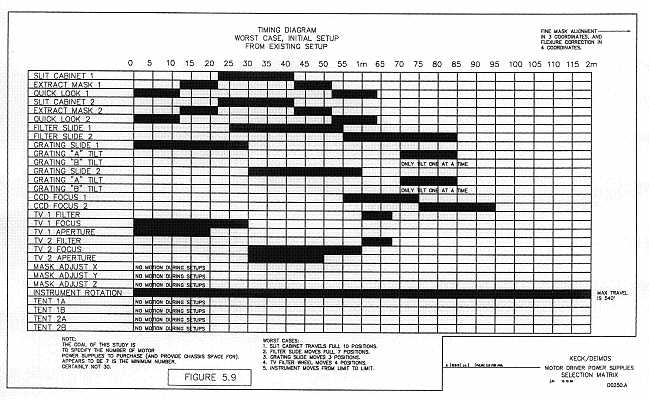
As discussed in Chapter 6, the dual-beam DEIMOS has 31 motors. To operate these
all simultaneously would require roughly 12 power supplies, an inordinate number. We
wish to reduce this number via an analysis like that shown in Figure 5.9, which is a timing
diagram for various set up times. In the version shown there, it takes a total of nearly 90
seconds to change masks and gratings using a sequence in which no more than 8 motors
run simultaneously. We reckon that this is a minimum plan. It would require 4 power
supplies (for the 8 motors) plus 2 extras (for insurance), for a total of 6. By careful analysis of real observing sequences we will fix the final number of motor supplies.
5.24 Mechanical Locating Tolerances and Deflections
The general approach to designing the Frame is to first lay out all the optical components so that the light paths are well defined and then locate steel structural elements making sure they clear all components and light paths. At that point you have a "strawman
design" to analyze. The location of the support bearings is done after the optical components have been located. This is because we are dealing with heavy components. The total
instrument weight is expected to be 9000 pounds. A grouping of optical elements naturally occurs near the front, or slit end, and so a large diameter bearing is placed at this end.
These optical elements include the two camera lens assemblies, two grating slides, the 36"
diameter window, and both of the slitmasks. Most of the weight of the instrument is carried by this large-diameter support bearing, probably 7500 pounds. The rear bearing is
behind the collimator mirror. It is located as close to this mirror as possible. The two bearings are separated by 90".
The tent mirrors are the most difficult to support. These mirrors must be suspended in
the center of the instrument, and the structure cannot block any light. The strawman fle ure of these mirrors is on the order of 0.002" of pure translation. Translations only move
the pupil around on the grating surface by minute distances. By the use of counterweights
the support can be designed to eliminate rotation of the tent mirrors. Rotation of the tent
mirrors is a problem since this moves the image at the detector. One arcsec of rotation of a
tent mirror will cause an image at the detector to move by roughly 0.2 pixels (3 µ) in
imaging mode.
The correct stability goal is 0.1 pixel at the CCD mosaic (1.5 µ). The total of errors
due to flexure cannot exceed this. These errors may be compensated by a flexure compensation system (FC system). This FC system is not finalized. We are hoping that it will be a
2-axis compensation system, that is, no rotation will be needed. We are looking at ways to
move the image around on the detector at the 30 µ (2 pixel) level. Likely candidates
include the tent mirrors, or the gratings in the grating slide stage. We are also thinking
about bending the detector/camera lens assembly using a device like an air cylinder to
apply forces. The dynamic range seems appropriate for this application: 30 µ total motion
and a 2 µ spec is 15:1. This means the pressure in an air cylinder needs to be controlled
from 100 psi down to 6 psi, and that is easy to do.
Mechanical design techniques will be used to minimize bi-metallic thermal problems.
The frame is all steel, but the camera cell is aluminum. This needs careful attention.
Structural design will attempt to have cancelling deflections where possible and take
advantage of parallelogram linkages to support elements inside the framework of DEIMOS. Parallel linkages will minimize rotations. Flex pivots will be used wherever possible so that backlash will not become a problem. This applies only to stages with small
motions, like the detector focus and slitmask fine-motion locators. The large-motion
stages will rely on rolling element bearings and will need clamps or locks once in position.
Kinematic mountings will be used wherever applicable.
Figure 5.10 as a first draft of the initial alignment specifications. This figure will be
used throughout the design and assembly of DEIMOS. This figure also summarizes our
preliminary estimates of structural deflections.
To summarize, the mechanical design of DEIMOS has taken the following steps:
5.25 Slitmask Error Budget
This section outlines an error budget for the location of slitlets in the focal plane.
There are two types of alignment requirements: slitlets to the sky, and slitlets to the detector. The first requirement is needed to align slitlets with astronomical objects in the field
of view. We discuss that first, for the case of one and then two beams.
The second requirement is needed to maintain the proper wavelength centered on each
pixel on the detector. This is needed in order to ensure that a calibration flat-field taken
through the mask at one time will successfully flatten an observation taken at another
time, allowing for the fact that the mask may have been removed and reinserted in the
interim. This requirement must met internally for each beam, and the case of one beam
vs. two does not arise.
Finally, there is the additional, highly desirable requirement that a mask can be
removed from a mask holder, stored, and reinserted successfully later.
It turns out that satisfying most of these requirements depends critically on the existence of fiducial markers in the focal plane. These are naturally provided as part of the
flexure compensation system, which is built around four rigidly located optical-fiber feeds
that provide four spots of light, two per beam, to the FC CCDs. These spots provide two
functions. First, they allow one to reset the internal optical alignment of each beam so as
to image a given spot in the focal plane repeatedly onto exactly the same pixel. That
ensures that a given slitlet, once properly located in the focal plane, will send all its wavelengths to the same set of pixels. A flatfield at one time will therefore agree in wavelength
with an observation taken at another time. Hence, with the aid of the fibers, alignment of
slits to the detector can be replaced by the equivalent notion of alignment to the fiber-optic
feeds in the focal plane, which is much easier to achieve.
The second function of the fiber-optic spots is to provide a "constant ruler" in the focal
plane. This provides a way of knitting together direct images from both beams by referencing each one independently to its fiber-optic feeds. This is needed in order to locate
masks made from double DEIMOS images the proper distance apart in the focal plane.
Note that alignment is critical in the x coordinate (perpendicular to the slitlets) but not
as important in y. The x coordinate is more important because the slitlets are narrow in
that direction and because the wavelength tolerance parallel to the dispersion (for flat-fielding) is tighter than the image tolerance perpendicular to the spectrum (see Chapter 7).
This section focuses only on the critical x coordinate.
5.25.1 Alignment of Slitlets on the Sky: One Beam
Slitlets can be misaligned with respect to the sky for several reasons, including mask
fabrication errors, mask placement errors, astrometry errors, tracking errors, and atmospheric dispersion errors. This section estimates the sizes of these errors for a single beam
and establishes an error budget for the components that originate within DEIMOS. The
goal is to keep DEIMOS' errors well below anticipated slitwidths. That appears to be feasible.
1) Mask fabrication: The specifications for accuracy in cutting the slitlets are con tained in the RFQ sent to laser cutter vendors, a copy of which is contained in Appendix E.
The x specification is 0.017" (13 m). Vendors have not expressed any difficulty in meeting this tolerance.
2) Thermal effects during mask fabrication: A difference between the use-temperature as predicted at mask fabrication vs. the actual temperature in the telescope may result
in a mask scale error. This is dealt with below under "Scale errors".
3) Astrometry: Typically a prior picture of the field will have been taken with DEIMOS, from which slitlet coordinates will have been derived. Astrometry tests have been
made with LRIS over the past year, for which random position errors are found to be typically 0.10" in x and y. We have a plan for doing astrometry with DEIMOS that should
reduce these by at least a factor of two. Assume 0.05" for this term.
4) Scale mismatch: Scale errors will occur if the mask material is temperature sensitive, if the structure defining the focal plane and mask holders expands or contracts, and if
the telescope focal plane scale changes. A thermal expansion coefficient for the focal
plane structure and mask material of 5 x 10⁻⁶ per degree C produces an error of 0.006" per degree C at
the edge of the 10' focal plane. However, effects within the x coordinate of a single mask
are only one-fourth as large because a) masks are narrow in the x direction (~5'), and b)
half of the effect of a stretch can be removed by relocating the x centroid.
Thermal changes within a night at Keck are small, typically less than 2 degree C, and mean
temperatures can be predicted on any given night to about the same accuracy. Let as
assume a 3 degrees C mismatch between the temperature of use (assumed at the time of cutting)
and the actual temperature. The maximum x position error would then be 0.0045" due to
thermal errors of manufacture, or 0.04 px.
Additional scale errors occur after insertion into the focal plane. One effect is due to a
change in focal plane scale caused by a thermal expansion of the primary mirror cell. This
turns out to be equal to the thermal effect on the masks above for the same coefficient of
thermal expansion (in fact they tend to cancel) and is therefore also of order 0.0045"
across a mask. Temperature also affects the focal lengths of the individual segments and
the secondary mirror. However, because these elements are made of Zerodur, these
changes are tiny. A final effect is caused by focus error -- the RC field is not telecentric --
but again, the effect is only of order 0.01" for any plausible out-of-focus error.
The net result is that position errors in x across a mask due to scale errors should be
small. Conservatively we adopt 0.01" for this term.
Note that we plan to set up astrometric standard fields that can be used to verify
quickly that the focal plane scale is within tolerance.
5) Alignment: Masks will be aligned by placing pre-selected guide stars within
square holes (see Section 9.6). Assume as above that the astrometric error for these stars
is 0.05" (from previous DEIMOS images). Assume also that the position of an individual
star can be measured with respect to its hole by 3% of its FWHM, or 0.03" in poor seeing.
Since a mask is long and thin, aligning in x uses up roughly two degrees of freedom -- the
mean x coordinate and rotation. Hence, N alignment stars provide N-1 independent measurements. If N = 5. the net error in the x coordinate is therefore 0.058"/4, or +/- 0.029".
6) DEIMOS position angle: The specification on tracking accuracy in DEIMOS PA
is +/- 8.9". At the ends of a 16.6' slit, this translates to 0.044" in x.
7) Offset guider error relative to the focal plane: Even if the image tracks perfectly
in the guiders, there will still be an error of the guide TV relative to the focal plane. We
have included a rigid reticle attached to the focal plane to monitor this error and keep it
small. The accuracy is limited both by flexure of the reticle and also by the ability to centroid the reticle pattern in the TV. Assume +/- 0.05" TV px for this latter error (under 2 x 2
binning), which leads to an error of +/- 0.007" in the focal plane. This also corresponds to
a flexure of 5 µ, which sounds reasonable. Adopt both of these, for a net error of 0.01"
due to offset guider error.
8) Tertiary mirror: A tilt on the tertiary mirror within the footprint of a single beam
produces a displacement of the image at the Nasmyth focus. The pattern of these displacements rotates relative to the focal plane as the telescope tracks and cannot be corrected out. These errors set an absolute limit to the astrometric accuracy of the Nasmyth
focus. The specification for the Keck II tertiary is an rms tilt error of 1.2 microradians per
beam, which works out to +/- 0.008" if apportioned equally between x and y.
9) Telescope tracking: The inherent accuracy of tracking by Keck II is not known.
The only estimate available is the performance of Keck I, which has attained an rms (in
each coordinate) of 0.035". The errors are very long term and are seen as a slow wander
of the image centroid about zero in the TV guider. By all accounts these errors should not
exist, but they do. We assume the same value of +/- 0.035" for Keck II.
10) Atmospheric dispersion: Eventually we will have an atmospheric dispersion compensator (ADC) to remove dispersion. Until then, dispersion is largely under the control
of the observer, depending on the choice of zenith distance, slit position angle, and wavelength of observation. We assume a mean value of +/- 0.15" in x.
Table 5.1 summarizes these errors. The first group is under our control within DEIMOS; the second is not. Atmospheric dispersion will dominate performance in the near
term, but once the ADC is built, DEIMOS will be the limiting factor. Even so, the errors
will be adequately small compared to probable slitwidths of (at least) 0.50". In this table
we have assumed the PA tracking error expected with two guidestars. Performance with
only one guidestar needs to be explored more fully.
5.25.2 Alignment of Slitlets on the Sky: Two Beams
Implicitly in the preceding section we have used up all degrees of freedom in the telescope RA and Dec and DEIMOS' PA to align the slitlets on the sky. A second mask must
either be located accurately enough with respect to the first that no tuning is necessary or
extra alignment modes must be provided.
Consider the tolerances required if absolute accuracy is relied on. Then two requirements must be met: we must know exactly where (in x) to cut the slitlets in the second
mask, and the mask, having been cut correctly, must be located accurately in the focal
plane.
Information on where to cut the slitlets will come, in general, from a prior set of double-beam images from DEIMOS. We propose that, before these images are taken, each
beam of the spectrograph optics be aligned by placing the fiber-optic spots on their fiducial locations in the FC CCDs. This will ensure that the image of the field taken with the
science CCDs will be accurately zeropointed in x to within a fraction of a pixel. In effect,
if the mosaic of the science CCDs and FC CCDs is stable, DEIMOS takes a picture of the
whole focal plane of the telescope with the sky field superimposed. An error of +/- 0.1 px
for this zeropoint on the FC CCDs translates to an astrometric accuracy in the focal plane
error of +/- 0.011", which is nearly perfect.
Transforming this map of the sky into good slitmasks depends on being able to locate
masks well in the cutter and then being able to put the same masks accurately into the
focal plane. The x-coordinate of each mask is defined by the two tooling balls along the
long side that form part of the kinematic mount. We assume that accuracy of insertion into
a kinematic mount is +/- 0.0005-in., or 13 µ. Assuming that insertion errors vary randomly
and add gaussianly, masks in the separate beams will then differ in their x-coordinate separations by +/- 0.001-in, or 26 µ, or +/- 0.036" when inserted into the focal plane, compared
to how they were cut in the cutter. This is an additional error term in x for the second
mask if no extra alignment mode is provided for it.
This appears to be the biggest of error for the second mask. Temperature errors could
stretch the focal plane compared to the temperature at which the pictures were taken, but
the major part of this will be removed by centering the fiber-optic spots on the FC CCDs
when the direct images are taken. This term is small anyway. Furthermore the focal plane
will be constructed to be very rigid, and the separations between the fiber-optics feeds will
not vary. A tolerance of +/- 0.0002-in on this quantity under flexure translates to an error of
+/- 0.007" in the focal plane, or +/- 0.9 px on the detector.
The conclusion is that mask kinematic mount error, both in the cutter and in the focal
plane, will be the limiting source of error in the x position of the second beam. With good
planning, this error does not appear to be large. We are currently weighing whether it is
large enough to warrant the installation of the mask trim motors on the second side. Probably we will install these motors for safety's sake but not implement them unless they are
needed.
In practice the extra alignment error for the second mask would be shared equally
between the two beams, reducing it to +/- 0.018". This effect is added in at the bottom of
Table 5.1 but is negligible. Finally, if masks are reused, this will add an additional kinematic mount error to each mask (see below), which would multiply this term by sqrt2. It will
still be small.
5.25.3 Alignment of Slitlets to the Detector
If flat-field calibrations are to be long-lived, it must be possible to place a given wavelength from a given slitlet accurately and repeatedly onto the same pixel at all times. This
alignment may be disturbed by flexure of the internal optical elements and detector, and
by failure of the slitmasks to maintain position in the focal plane. The problem of internal
flexure is discussed in Chapter 7, where a Flexure Compensation system is outlined that
can successfully steer the beam. The slitmask problem is discussed here. It consists of
two parts -- motion of a mask during an exposure relative to the fiber-optic feeds, and rel cation errors of a mask during reinsertion.
As discussed in Chapter 7, our working tolerance for wavelength accuracy on a pixel
has been driven by the need for flat-fielding accuracy and has had the value +/- 0.1 px.
However, new estimates described in Chapter 7 suggest that this can be relaxed to +/- 0.25
px. Our tolerance for the motion of a mask in the focal plane relative to the fiber-optic
feeds during an exposure is extremely tight, +/- 4 µ, or +/- 0.05 px of motion on the detector.
So the effect of mask motion during an exposure will be negligible.
Relocation errors are a bigger problem. When a mask is reinserted, its kinematic
mount error of +/- 0.0005-in (see above) corresponds to a motion of +/- 0.15 px on the detector, which is a fair fraction of the error budget. Kinematic mount errors therefore have to
be watched carefully.
5.25.4 Reusable Masks
Since labor will have been invested in cutting the masks, it is highly desirable to be
able to reuse them. A definitive statement on feasibility cannot be made at this time as it
depends crucially on the choice of mask material. This is discussed further in Chapter 8,
but the choices are basically thin stainless steel or molded plastic. Plastic is attractive
because it offers a better choice of having masks in one piece rather than four separate
pieces, as seems necessary with steel. Either way, if masks are to be reusable, there must
be a way to relocate them accurately in the mask frames.
A way to do this would use a second, quasi-kinematic mount within each frame. We
call this a quasi-kinematic mount because two points would be used instead of three. Two
grommet-like fixtures would penetrate each mask at either end and fit kinematically into a
cone and groove on the frame (mask tip is controlled by the clamp and is not important
here). This second kinematic mount would add another 0.0005-in uncertainty to the x
coordinate position, or 0.15 px on the detector, or 0.017" on the sky. The latter error is
small compared to the centering error budget in Table 5.1, so reusing masks should contribute negligibly to astrometric error. The pixel shift on the detector could be significant
for flat-fielding but, if important, could be dealt with by taking another flat field.
A caution is that it is very unlikely that all frames can be made with distances between
tooling balls and the internal kinematic mounts uniform to 0.0005-in. That means that a
mask, to be reused, must be reinserted into the same frame. Hence frames will have to be
labelled, and records kept of mask/frame combinations.
We conclude that reusing masks seems feasible and it is worth looking hard for a
method of mask fabrication that would make this possible.
Finally we note that the discussion in this and the previous section has assumed the
prevailing wavelength-shift theory for the origin of flat-fielding errors. The discussion in
Chapter 7 raises some doubts as to whether this origin is correct. If not, the critical tolerances on the kinematic mounts set here could be relaxed somewhat, though astrometric
errors would still continue to be a factor.
Source Amount1 DEIMOS: Mask Fabrication 0".017 DEIMOS Astrometry 0".05 Scale/Thermal Errors 0".01 Alignment Stars 0".029 DEIMOS PA 0".044 Offset Guider 0".01 Total2 DEIMOS 0".076 Telescope and Atmosphere: Tertiary Mirror 0".008 Telescope Tracking 0".035 Atmospheric Dispersion 0".15 Total Telescope 0".154 Total Telescope with ADC3 0".039
Total System: (First Beam) Total 0".172 Total with ADC3 0".085 Total System: (Second Beam)4
Total 0".173 Total with ADC3 0".087
    1 Values shown are the rms error of the slitlet locations in x coordinate.
    2 Totals are obtained by adding in quadrature.
    3 ADC will reduce atmospheric dispersion errors by about a factor of 10.
    4 Assumes second-beam alignment error shared equally by both beams.
GO TO CHAPTER 6